The design of the "KOOSHK Bagh" Villas Complex in Namak Abroud was a project that, from the very beginning, when selecting and purchasing the land, required coordination between the client, builder, and investors. In this project, we drew inspiration from the structure and layout of the "Koushk," a traditional Iranian villa in persian gardens, typically built for prominent individuals and higher social classes and These buildings are known for their outward-facing design. Three different designs were proposed for three separate plots of land. In the end, two modern designs were selected, updating the principles of traditional Iranian architecture.
حیاط سبز با کف ُ و سقف اختصاصی
ورودی واحد
ورودی واحد
حیاط سبز با کف ُ و سقف اختصاصی
اسپاتراس
فضای بسته واحد ویلایی
135 مترمربع
فضای بسته واحد ویلایی
135 متر مربع
Structure
Site Area
850 :
m2
مجموع مساحت فضای باز و بسته هر واحد ویلایی 180 متر مربع
اسپاتراس
The above design embodies a new concept and lifestyle for the villa complex: first, there are no shared walls between the units on each floor, and the vertical connection core (staircase and elevator) completely separates the two units. Second, the characteristic of a villa unit in the mind of an Iranian is that, upon entry, there should be an open green space. Therefore, at the entrance of each unit, a spotras (a modern enclosed open space, similar to a ghulam-gardesh in traditional Persian architecture) and a yard with a two-story pitched roof (modeled after the Iwan of Ali Qapu in Isfahan) were designed, offering a pleasant view of both the sea and the mountainous landscape of Namak Abroud. Interestingly, the floor of the courtyard structures next to each unit is not the ceiling of the lower unit, as the courtyards alternate between floors, creating a special space for children's play and family gatherings.
The design below is the second option for the Kooshk Bagh project in Namak Abroud
In this design, a distinctly Iranian plan pattern of 9 squares was used, a design seen in both pre- and post-Islamic "KOOSHK"s in Iran, applied in various ways in both outward-facing and inward-facing pure Iranian architecture. The six-story building features four dynamic and interconnected facades. In the design of the outer volume of this 10-unit villa complex, there are 14 two-story terraces, each measuring approximately 4 by 5 meters. These terraces are arranged in a spiral pattern around the building, offering a pleasant view of the mountains and the beach of Namak Abroud, without overlapping each other. Given the shifting and rotation of the terraces on each floor, six different plans were created to accommodate various preferences. Thus, the floor plans were designed to ensure the functionality and aesthetic balance of the space
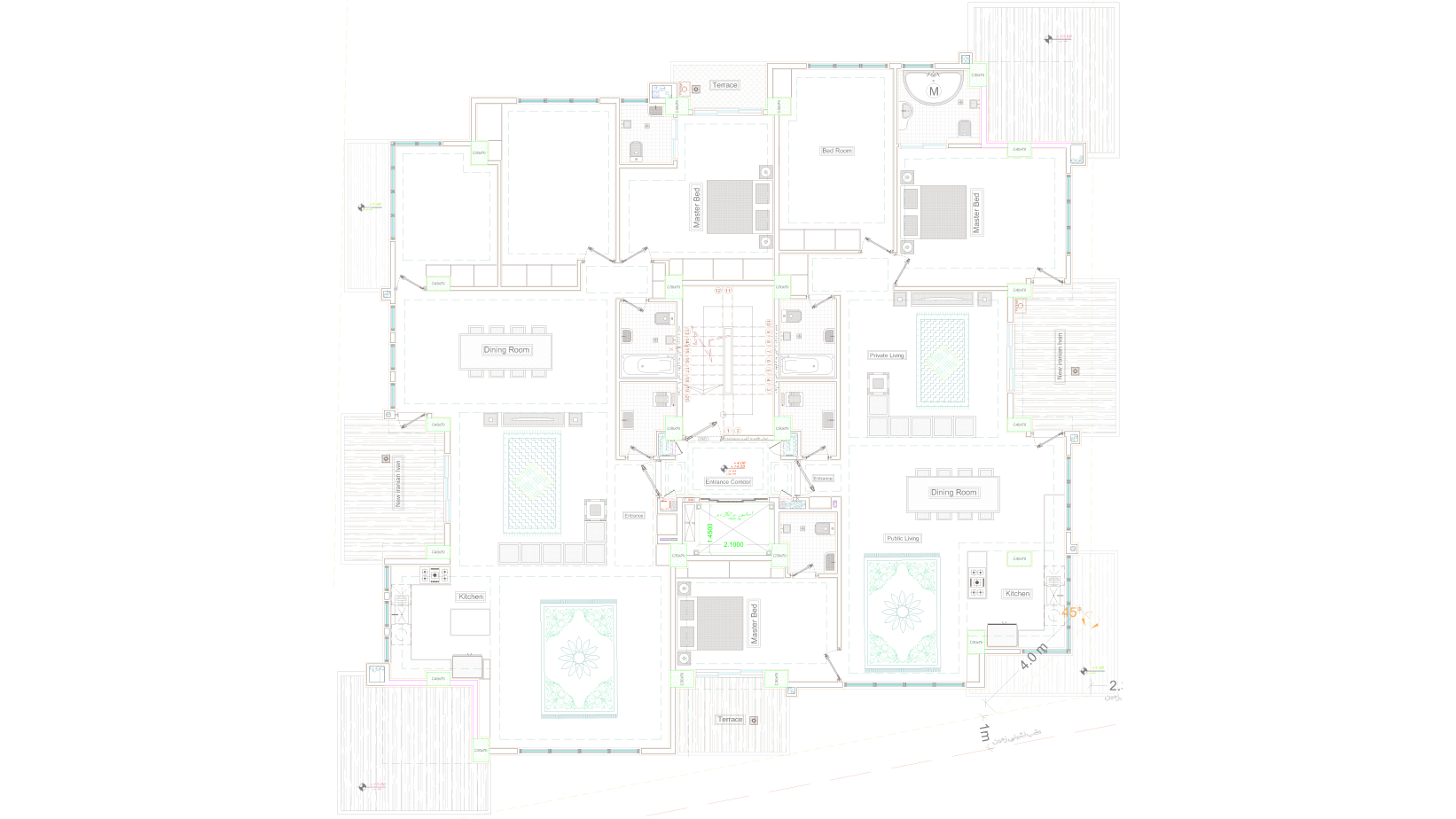
First and Fourth Floor Plans: In this design, the terraces are positioned in central areas of about 15 square meters, serving as the focal point of the house. They create a pleasant space for family gatherings and offer a flexible area for various functions. One of the key features of traditional Iranian floor plans is the adaptability of each space’s function, and this concept has been applied here as well. For example, depending on the inhabitants' preferences and the weather conditions, these terraces can serve multiple purposes. By simply placing a 12-square-meter Iranian carpet, they can function as an outdoor sleeping area, a space for midday meals, a reception area for guests, or even as an extended platform for enjoying the beautiful natural views of Namak Abroud.
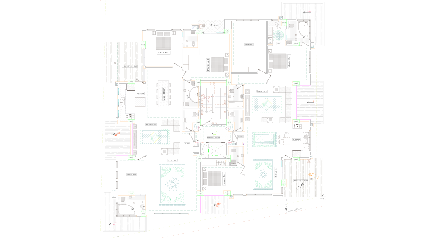
Second and Fifth Floor Plans: Terraces, spanning nearly 20 square meters at the outer corners of the plan, on the northwest and southeast sides, are situated adjacent to the dining area, kitchen, and living room, allowing them to function in conjunction with all these spaces and facilitate access and service. Each unit comprises 170 square meters and features three bedrooms, with the parent and guest bedrooms each having a private en-suite bathroom.
A crucial consideration in the arrangement of wet and dry areas within this villa complex is that a wet space, such as a bathroom or kitchen, is located beneath each terrace on the lower level. This design allows for the integration of rainwater pipes within the suspended ceiling of the wet space below, connecting them to the plumbing riser and utility duct.
Furthermore, access panels to the main plumbing riser for each unit are provided in the elevator lobby of each floor. The majority of wet areas within the units are connected to this main riser. The significance of these access panels lies in their ability to greatly simplify future renovations and replacements of utility pipes
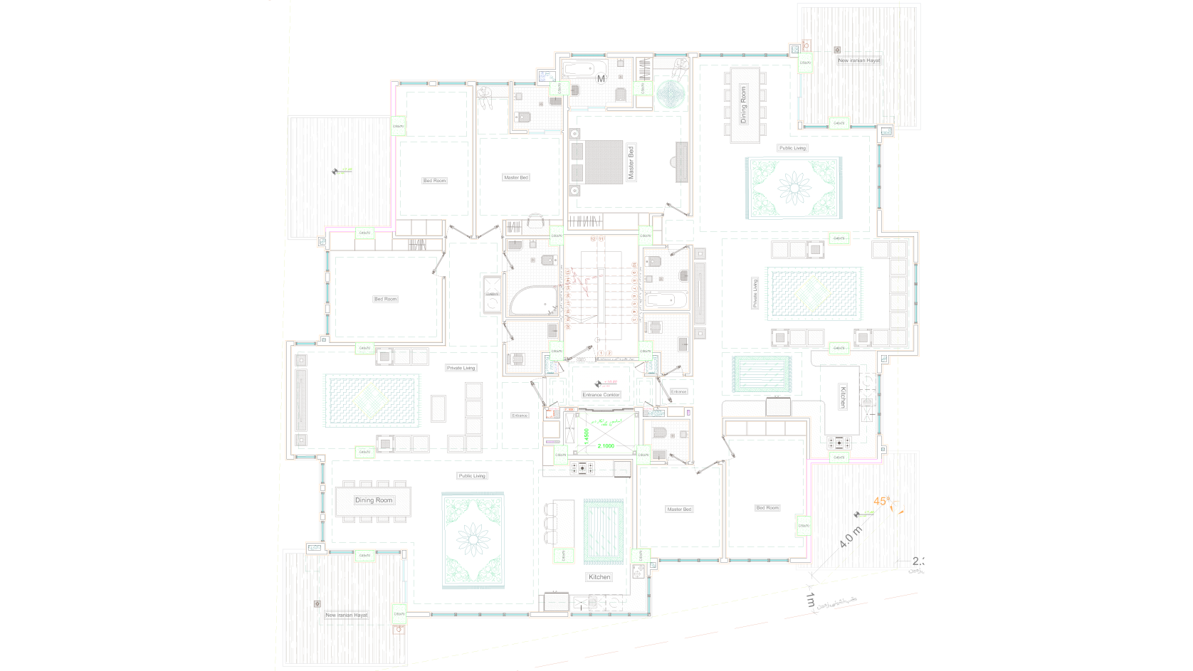
Third Floor Plan: Terraces, spanning nearly 20 square meters, are situated at the corners of the plan, on the northeast and southwest sides, adjacent to the dining area, living room, and reception area. This layout is designed to allow the terraces to function in conjunction with all these spaces, facilitating access and service.
A crucial detail observed in the spaces of this villa complex is that no windows or openings face the terraces of units below, ensuring privacy between units. Consequently, the green walls placed on the terraces can grow up to two stories high, creating a green facade that blends harmoniously with its surroundings
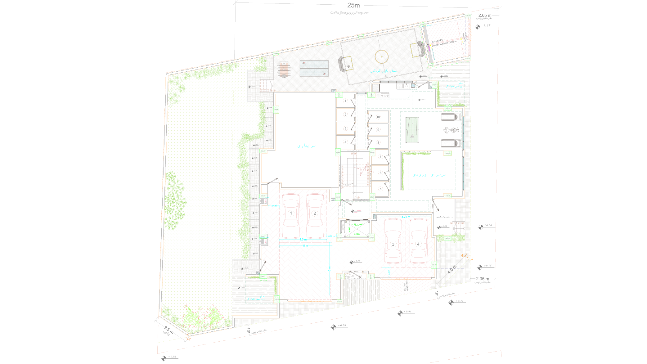
Ground Floor Plan: The site area of this villa complex is approximately 850 square meters after setbacks, and the permissible building footprint for each floor, according to the planning guidelines, is 450 square meters
This site is situated on a three-corner plot, accessible from a 12-meter passage to the east, an 8-meter passage to the south, and a 6-meter passage to the west.
We designed the parking entrance from the southern 8-meter secondary passage and the main pedestrian entrance from the eastern 12-meter main passage for better visibility and security.
Additionally, we incorporated amenities such as a children's play area, a gym, a communal kitchen, individual unit storage rooms, a caretaker's residence, and a family gathering space with a view of the green space, ensuring these areas are completely separated from the vehicle parking area
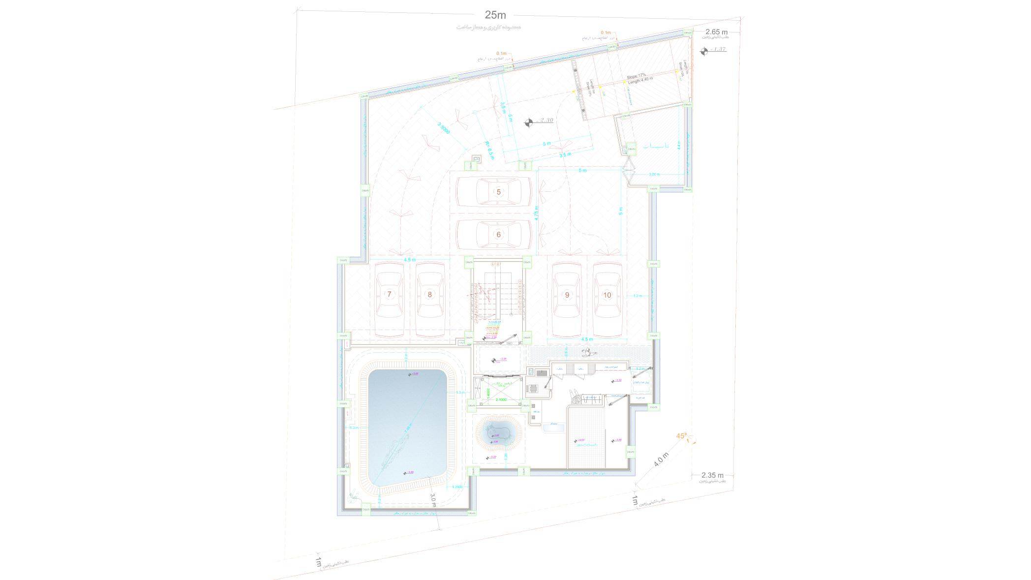
Basement Floor Plan: Following the land survey and mapping, we identified an approximate 1.8-meter level difference between the north and south of the site, which provided us with an excellent opportunity to design optimal parking ramps.
The lowest ground level is located on the northeast side of the site, making it the ideal location for the vehicle entrance to the basement.
The northern half of the plan was designated for vehicle parking, as this allowed us to position and design the shortest possible ramp length.
In the southern half of the plan, a family swimming pool and its necessary equipment and utilities were designed
In completing the execution plans for this complex, our team faced two main challenges that required coordination to resolve,
as outlined in the following points :
"Challenges in Designing Wet Area Plumbing and Ventilation:
The rotation of the terraces around the building's volume led to a variation of the unit plans, resulting in the design of six different floor plans for the villa complex.
Consequently, a challenge arose in identifying common points between wet and dry areas that aligned vertically across floors and were suitable for routing utility ducts. Our team, with a general understanding of the building's mechanical and electrical systems, resolved this issue through coordination and approval from the mechanical project engineer.
"Challenges in Concrete Structural Design and Calculation for Cantilevered Terraces and Integrated Building Systems"
In the design of the terraces, which project like platforms cantilevered from the building's volume, we created cantilevered beams extending approximately 4 meters from the columns. To address this challenge, simultaneous architectural and structural design coordination within our team was necessary.
This architectural and structural coordination also led to coordination between structural and mechanical, electrical, and plumbing (MEP) systems. Utility ducts were routed through areas where main beams and joists did not pass, and where necessary, some beams were slightly repositioned during the design and calculation process
Its time for mutation
Look at the universe differently
Phon: +982186093714
Tehran, No. 81, Forsat Shirazi Street, Hirad Office Building
afagh_arch@yahoo.com
سَنُرِيهِمْ آيَاتِنَا فِي الْآفَاقِ وَفِي أَنْفُسِهِمْ
021-86093714 : تلفن
تهران خیابان فرصت شیرازی ساختمان اداری هیراد پلاک 81